
Mounting Piezoelectric Force Transducers
Preload, parallel force paths and fixture dynamics determine installed measurement behavior. Use this engineering checklist before choosing a quartz force ring or link.
Peak force · pulse duration · mounting envelope · signal output · existing DAQ · quantity
Compare the QPF families →Preload, force shunt and installed sensitivity
A center bolt keeps the quartz ring compressed, but also bypasses part of the incremental force. Select preload from the exact sensor and hardware instructions. Around 20% of nominal force appears in some manufacturer guidance; it is not a universal QPF setting.
Check total compression with preload, tensile unloading, contact faces and bolt stiffness. Calibrate the installed assembly. Torque alone is not a direct measurement of preload.
Explore a preloaded QPF-LNK assembly →Read the mounting and bandwidth guide →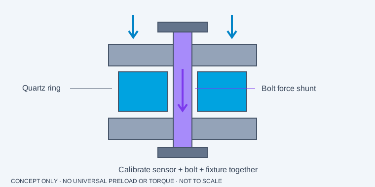
Set preload from the exact ring and force direction
- Record peak compression, tension/unloading, preload and allowable total compression. Avoid loss of crystal compression during tensile unloading.
- Prepare clean, flat, parallel mating surfaces. Keep side load and bending out of the intended axial path.
- Use the approved bolt, washers, insulation and lubrication. Record hardware material and tightening procedure.
- Monitor preload with the specified measurement method. A generic torque value does not establish force.
- Calibrate the ring and fixture together. Changes to the bolt or parallel structural path change the force shunt.
Resonance is not the usable frequency response
The sensor, attached masses and fixture create a mounted response. Keep your required flat response band below the relevant resonances using the model’s specified amplitude error, then confirm with the mounted setup. No universal fraction of resonance is asserted.
Calculate the electrical range before wiring the PLC
For an illustrative charge sensitivity of −4 pC/N and a 10 kN force, the expected charge change is −40,000 pC. At an illustrative gain of 0.1 mV/pC, the magnitude becomes 4 V. Match polarity, headroom and input limits; these numbers are not QPF ratings.
For an illustrative IEPE sensitivity of 1 mV/N and 2 kN, dynamic swing is 2 V. That is superimposed on the sensor’s DC bias. Check supply compliance and coupling before connecting an input.
Keep charge noise and thermal drift out of the result
Charge-mode cables can produce triboelectric noise when moved. Use qualified low-noise cable, secure it, protect the connector from moisture and maintain insulation. IEPE reduces output impedance but still has cable-drive and current limits. High-temperature sensor selection does not qualify every cable or amplifier for the same temperature.
Manufacturer references for the measurement principles
PCB force sensor operation manual: preload and measurement limits (PDF)Kistler ring force transducer instructions: force shunt and installed calibration (PDF)HBK / Dytran 1051V: reference IEPE force sensor familyThese sources describe their manufacturers’ products and general principles. They do not validate QPF product specifications.
Reviewed 5 November 2026 · QPF Dynamic Metrology engineering editorial.
Describe the event.
We’ll review the chain.
Include the peak force and pulse duration, your mounting space and existing DAQ. For replacements, add the complete original model and sensitivity.
Request a configuration quote, CAD availability and the calibration documentation you need.
[email protected]No checkout or automatic purchase. Accessory amounts are optional planning references; dimensions, compatibility, price and delivery require confirmation.