
Impact and modal tests
Submit contact duration, expected peak, impactor mass and mounting stiffness. A modal hammer includes a complete mechanical assembly, not just a force sensing element.
Capture the force-time history of an impact or press-fit cycle with a sensing chain selected for the pulse duration, fixture dynamics and acquisition bandwidth.
500 N–220 kN peak-force requests · IEPE or charge configuration. Selection envelope; confirm the exact model.
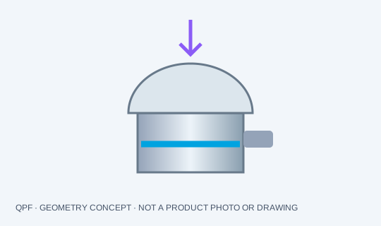
Submit contact duration, expected peak, impactor mass and mounting stiffness. A modal hammer includes a complete mechanical assembly, not just a force sensing element.
Charge amplifiers with controlled reset can support defined measurement windows. Slow dwell accuracy depends on leakage, drift and the entire time constant.
A target resonance above 75 kHz is not a guaranteed flat bandwidth. Confirm the mounted transfer response and the frequency range needed by the actual pulse.
Specify usable analog bandwidth, anti-alias filtering and sampling together. More samples do not restore information lost to analog clipping or fixture resonance.
Request a configuration-specific drawing and calibration record. Confirm rated load, direction, preload, sensitivity, polarity, flat response band, thermal range and overload limits. Discuss the required acceptance test before freezing the order.
Piezoelectric force measurement decays with system leakage and time constant. Share the cycle and allowed drift; for continuous dead-weight measurement use a suitable static sensing method.
Yes, if the full chain is verified for the chosen output, sensitivity, current or charge input, signal range, bandwidth, cable construction and connector. QPF accessory choices are optional.
A center bolt keeps the quartz ring compressed, but also bypasses part of the incremental force. Select preload from the exact sensor and hardware instructions. Around 20% of nominal force appears in some manufacturer guidance; it is not a universal QPF setting.
Check total compression with preload, tensile unloading, contact faces and bolt stiffness. Calibrate the installed assembly. Torque alone is not a direct measurement of preload.
Explore a preloaded QPF-LNK assembly →Read the mounting and bandwidth guide →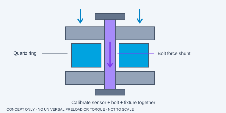
Include the peak force and pulse duration, your mounting space and existing DAQ. For replacements, add the complete original model and sensitivity.
Request a configuration quote, CAD availability and the calibration documentation you need.
[email protected]No checkout or automatic purchase. Accessory amounts are optional planning references; dimensions, compatibility, price and delivery require confirmation.